Roles:
• Promoted to Lead Mechanical Engineer in April 2023
• Served as Suspension Lead Engineer after Janurary 2023.
• Started as Suspension Engineer in August 2022
Achievements:
• Joined a team under 20 members with no advisors, and expanded it into a well-structured team of over 60 members, 4+ advisors, dozens of sponsors, and substantial funding, all within two years.
• Coordinated the completion of the V1 ‘proof-of-concept’ car, which did not adhere to FSGP regulations but did help the team move forward with the new V2 design.
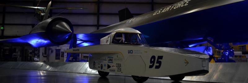
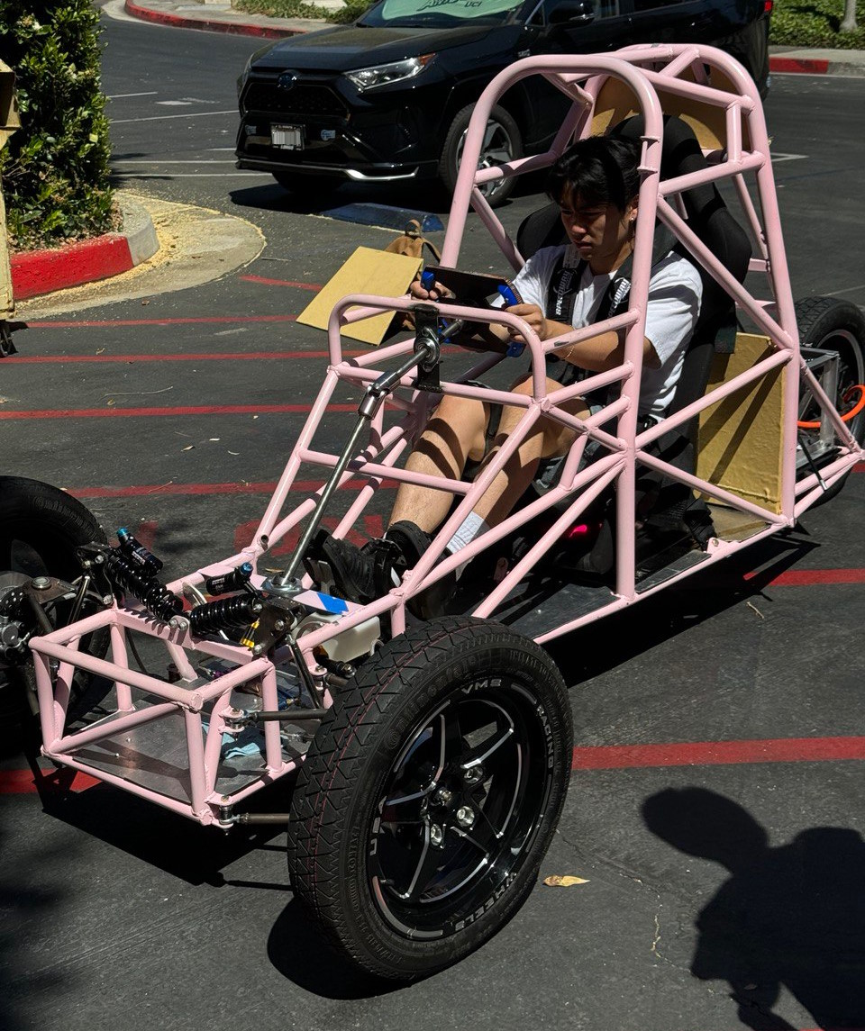
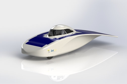
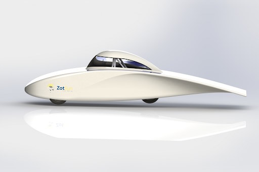
• Created “SolEater” — a solar-powered race car — from scratch, as its lead designer from start to finish.
• Garnered the project a prestigious reputation within the Henry Samueli School of Engineering.
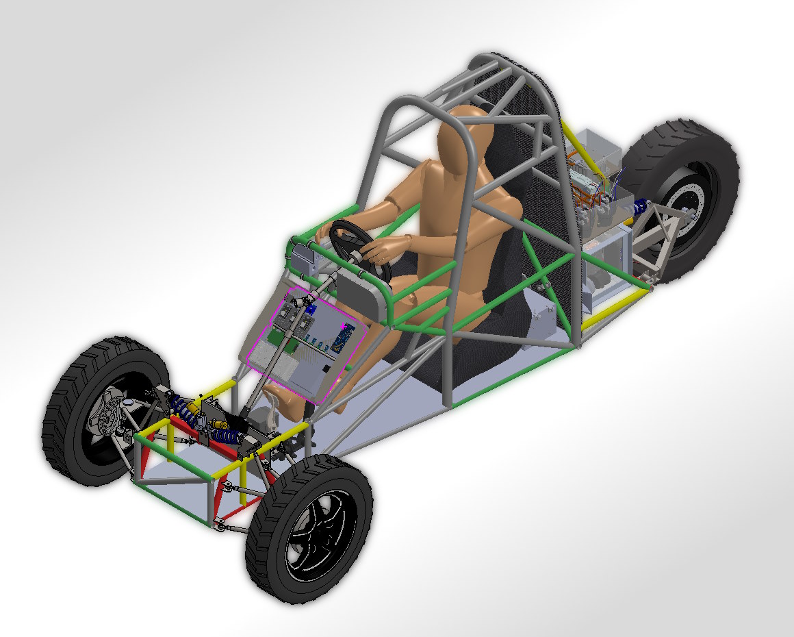
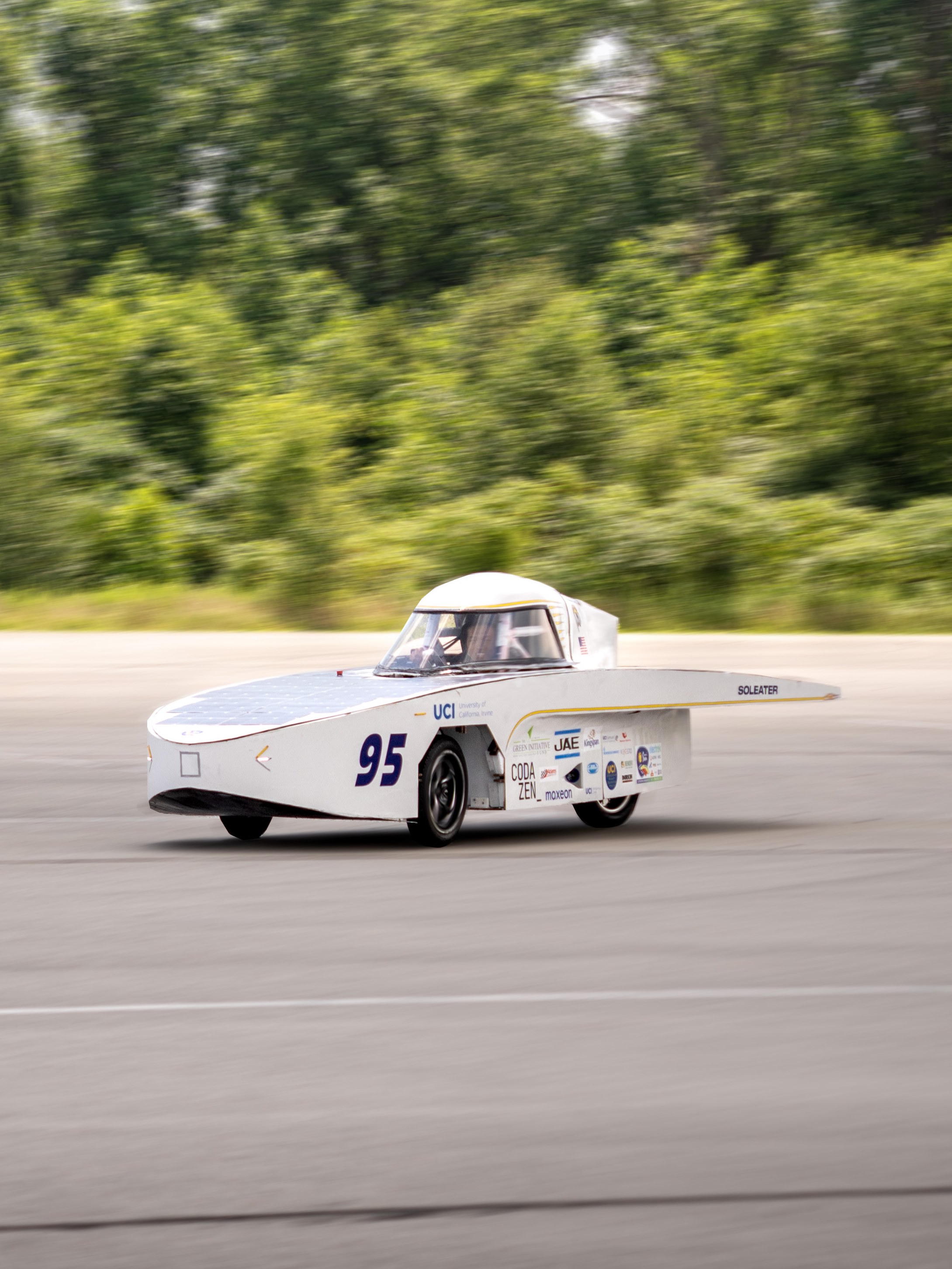
SolEater
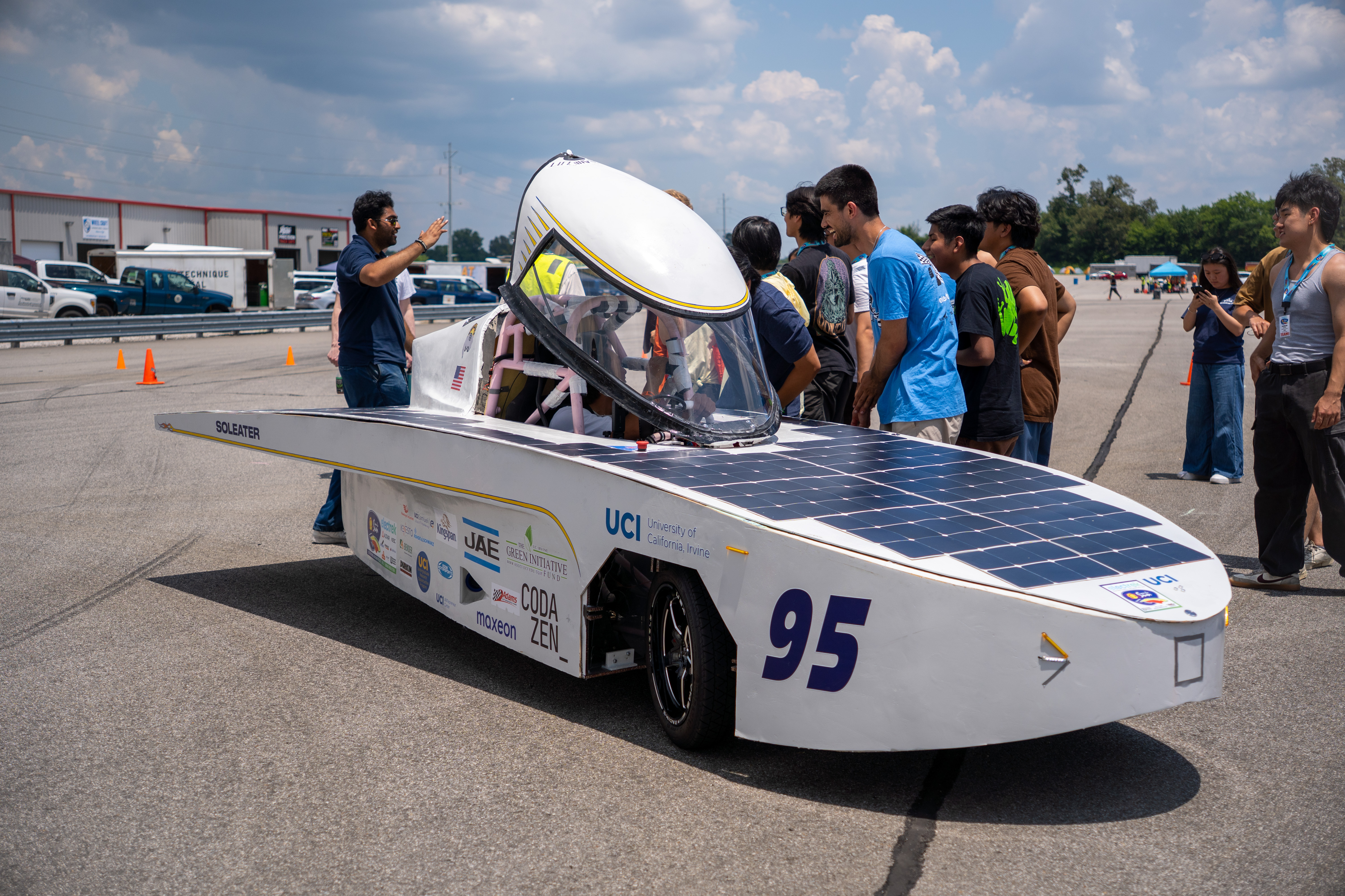
UCI’s first-ever ‘Solar Raycer’, a single-seater race car powered entirely by the sun, began its design phase in April 2023 and competed in the Formula Sun Grand Prix (FSGP) in July 2025, hosted in NCM Motorsports Park in Bowling Green, KY.
SolEater passed all technical inspections, a milestone no other UCI automotive team has achieved in their debut competition. It also completed dynamics testing, which includes a U-turn, slalom, and figure-8, with no issues during the event.
Technical specifications
• Weight: 570 lb (258 kg)
• Solar area and output: 5m2 | 800W
◦ Under nominal outdoor conditions, including efficiency losses.
• Battery capacity: 3.8 kWh
◦ 96V system
• Cruise speed: 37 mph (60 kph)
◦ Sustained purely with solar energy on flat ground
• Top speed: 67 mph (111 kph)
• Drag coefficient: 0.119
◦ For reference, a Tesla Model 3 has a Cd of 0.219
• Length: 195 in (5m)
• Width: 55 in (1.4m)
• Wheelbase: 94 in (2.4m)
• Track width: 47 in (1.2m)
Suspension
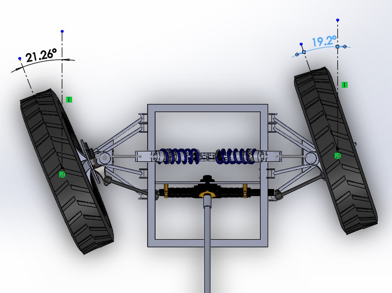
SolEater features a 3-wheeled design with double-wishbone front suspension, trailing-arm rear suspension, and a rack-and-pinion steering system with 91% Ackermann geometry (like a Porsche 911 or Miata). In its neutral position, with the driver onboard, the car has a 3.9° caster, 0.2° toe angle, and 0.1° camber, with a ride height of approximately 6 inches, and a turning radius of about 20 feet (we needed 30 feet or better for dynamics).
We considered using a bell crank design to reduce weight, but the FSAE-grade steering rack was easy to implement, reliable, and afforded much less margin for error in this critical error. The brake systems are fully independent front and rear hydraulic circuits with a bias bar and proportioning valve to optimize braking performance.
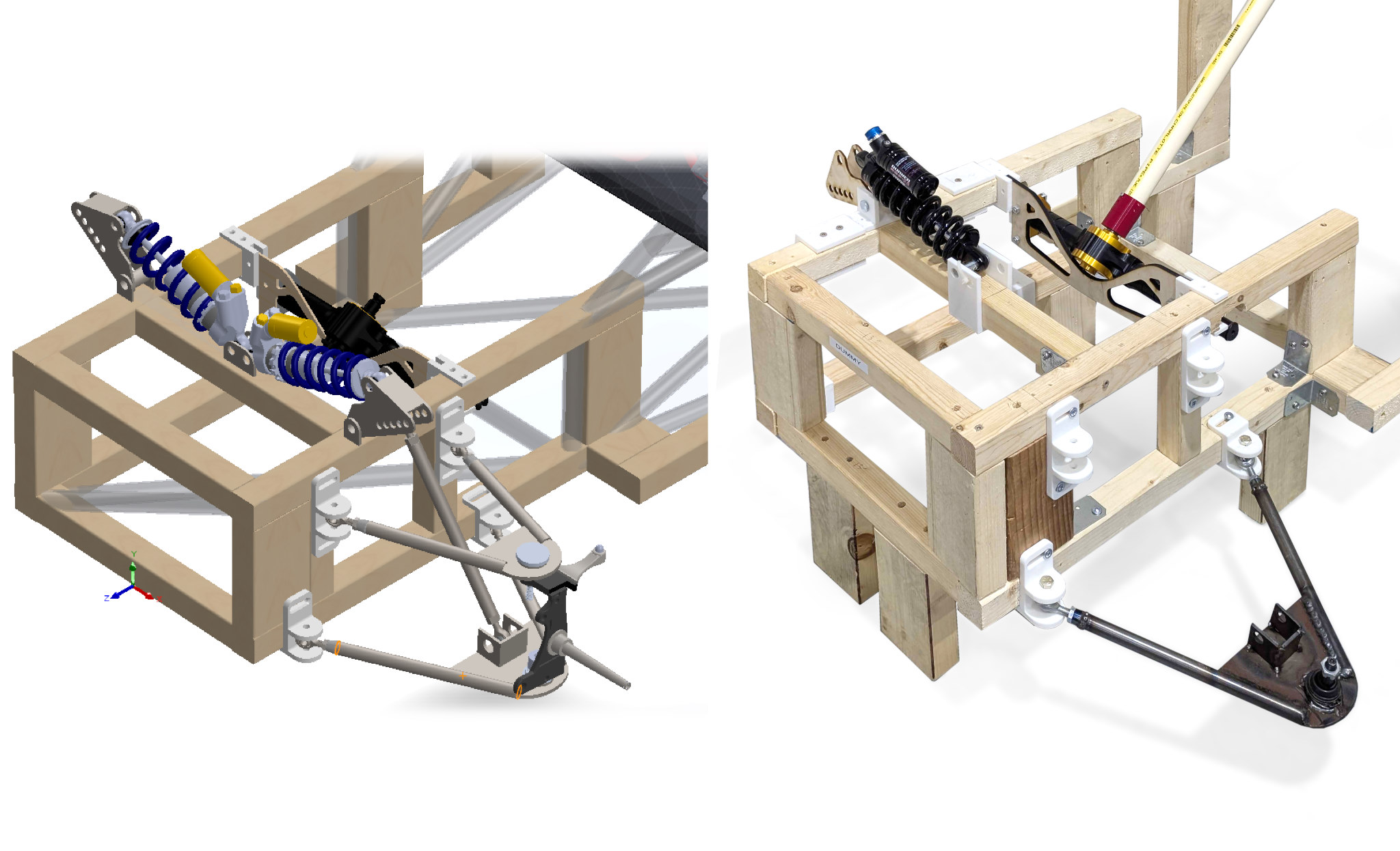
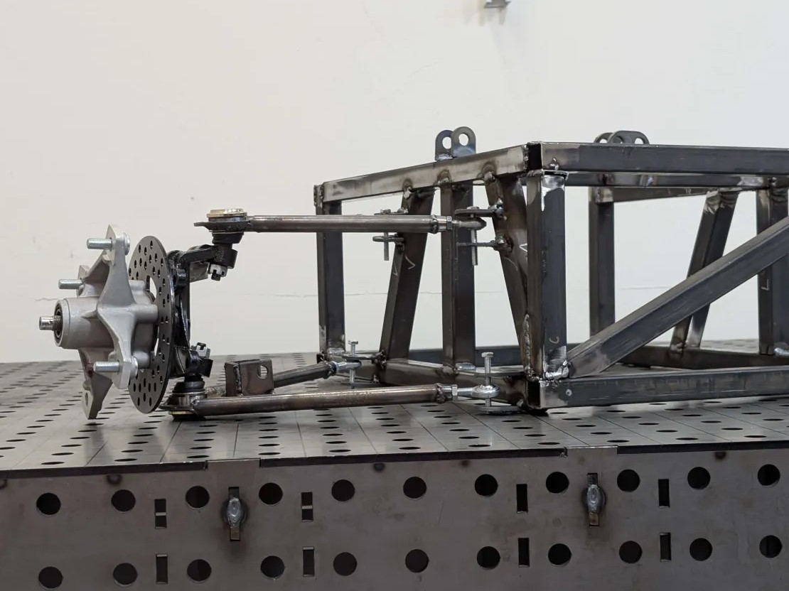
Front double-wishbone
As this was both the team’s first vehicle and my first automotive design, I prioritized the most important factor for a sun-powered endurance race: efficiency. We need SolEater to be more efficient than traditional race cars in every aspect of performance because every kilowatt of energy saved adds up to miles and miles of extra range.
At the time, my knowledge was limited, so I set my focus as the vehicle weight and the tire’s contact patch. Weight was considered as sprung and unsprung mass, and the contact patch was scrub radius and camber change rate.
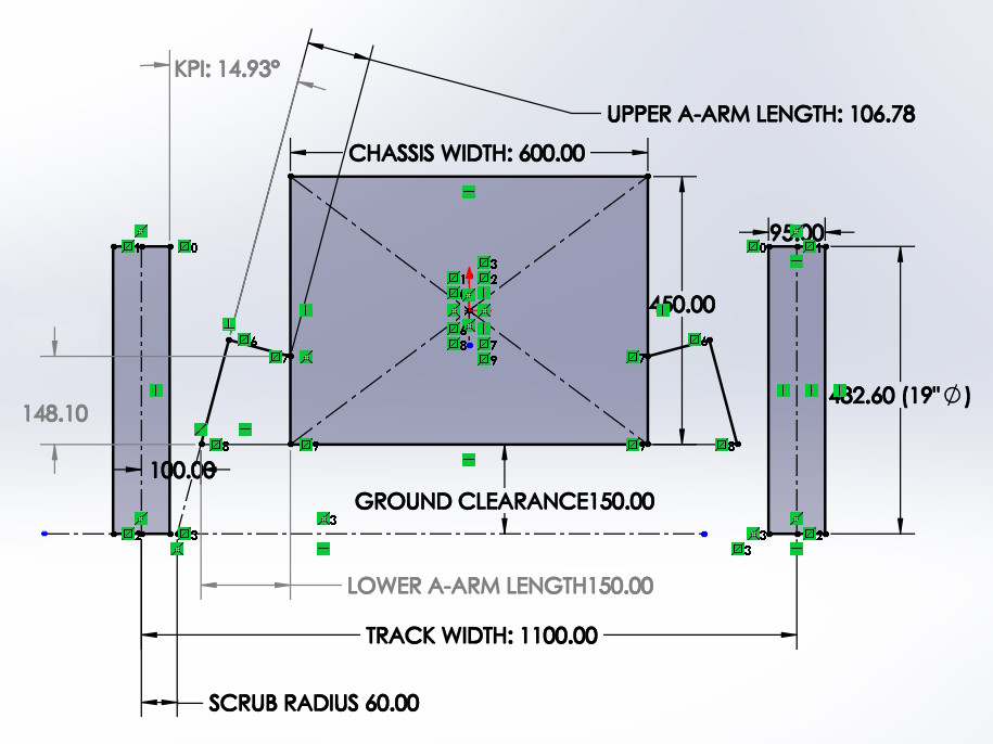
Along with the lead suspension engineer, I used SolidWorks to sketch rough dimensions for the components. Initially, we were advised to use ATV control arms, but after reverse-engineering them, we concluded that it would be more efficient to create custom A-arms: We could make them lighter, more compact, and better suited for our needs. This also gave us far more freedom in our design, which was great in hindsight, because we eventually had to slightly increase the track width to make the car more resistant to tipping, and to allow the aerobody a smoother curve around the nose.
Our biggest innovation was using parallel control arms, which effectively threw our instant center out to infinity and dramatically reduced the roll center height (RCH). Thus, we minimized our camber change rate, which meant that the contact patch changed very little over the travel of the wheel— we could have near zero camber under almost all track conditions, maintaining a consistent contact patch. However, we later realized the lower RCH does lead to more body roll, affecting cornering performance, but this tradeoff allows for a more compliant ride, which is ideal when a single driver must spend several hours on the track before a driver change.
Development started in May 2023, but it really started coming together in February 2024. By then, we were well-into designing our own A-arms. The suspension geometry was finalized a year later. In that time, we completed hundreds of simulations, created our own calculator spreadsheets, and gained an in-depth understanding of suspension design as well as the challenges of road and race vehicle dynamics.
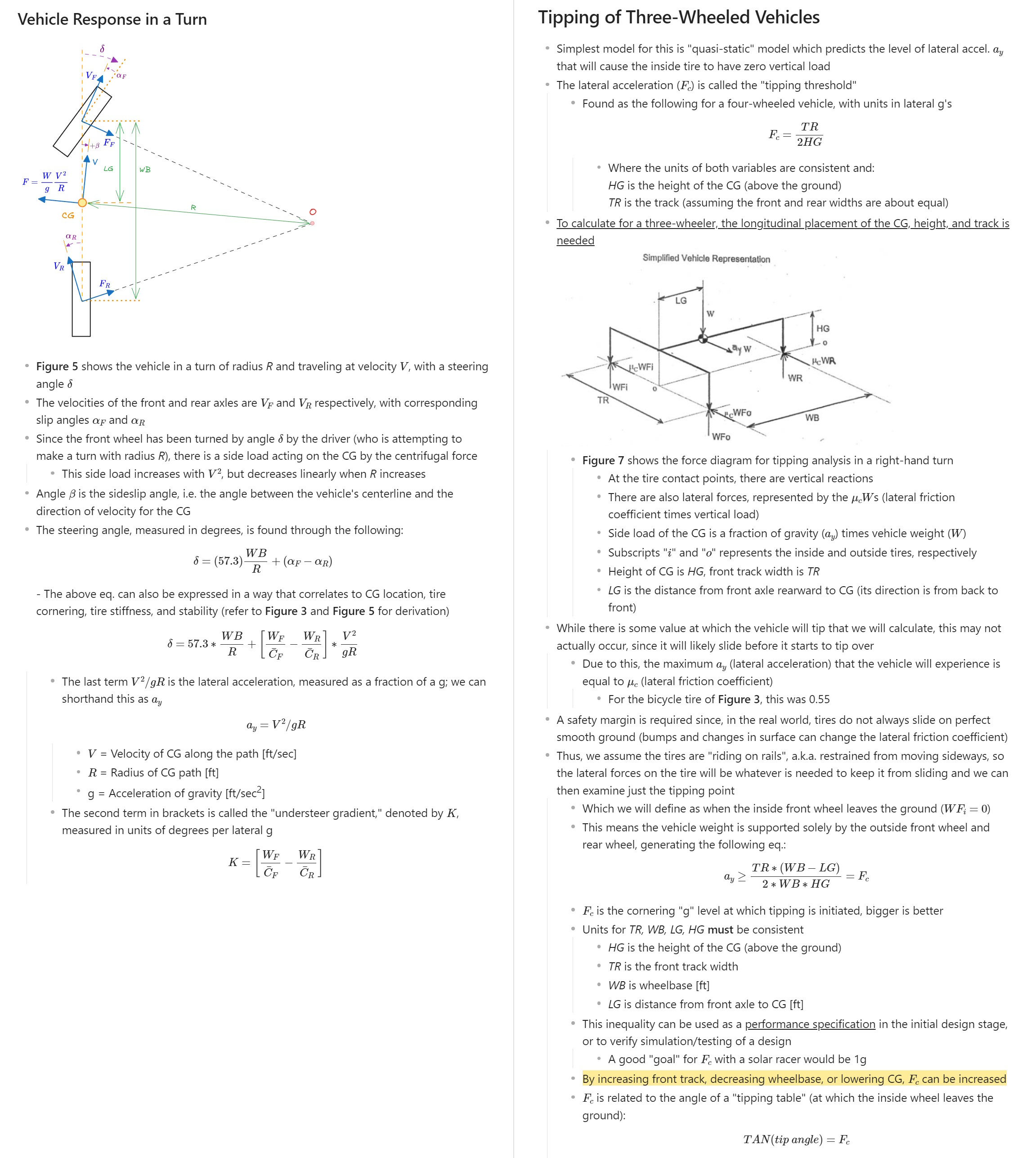
Knowing what I know now about understeer gradient, tipping stability, cornering stiffness, etc. I wish I created a much more efficient and performant design. However, since I had engineered SolEater as a lightweight race car rather than a typical solar car, it performed far better than we expected in dynamics testing, especially after adjusting the toe so slightly to increase the turn-in under load. Thanks to this agility, we were able to beat out many of the other teams in stability and driver confidence.
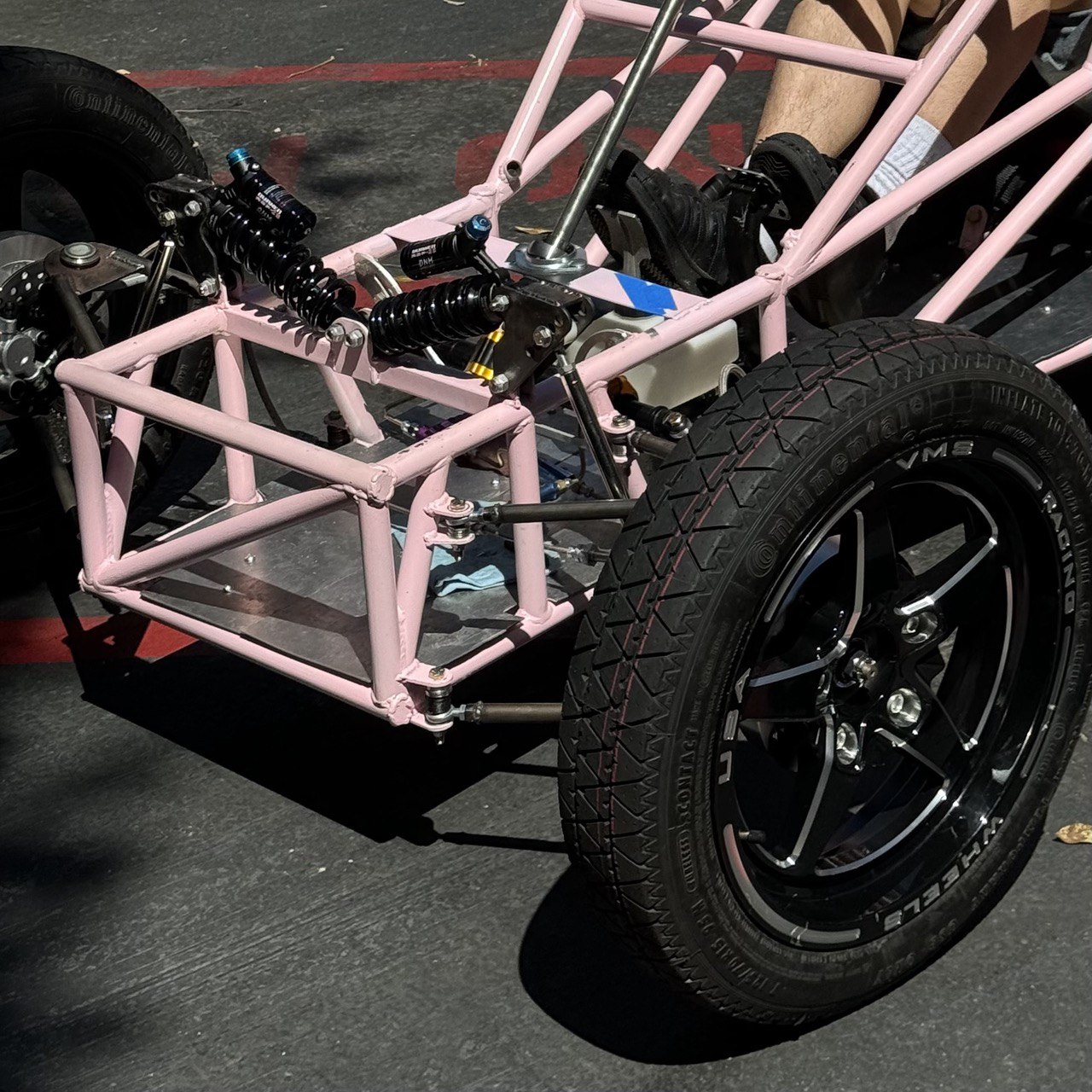
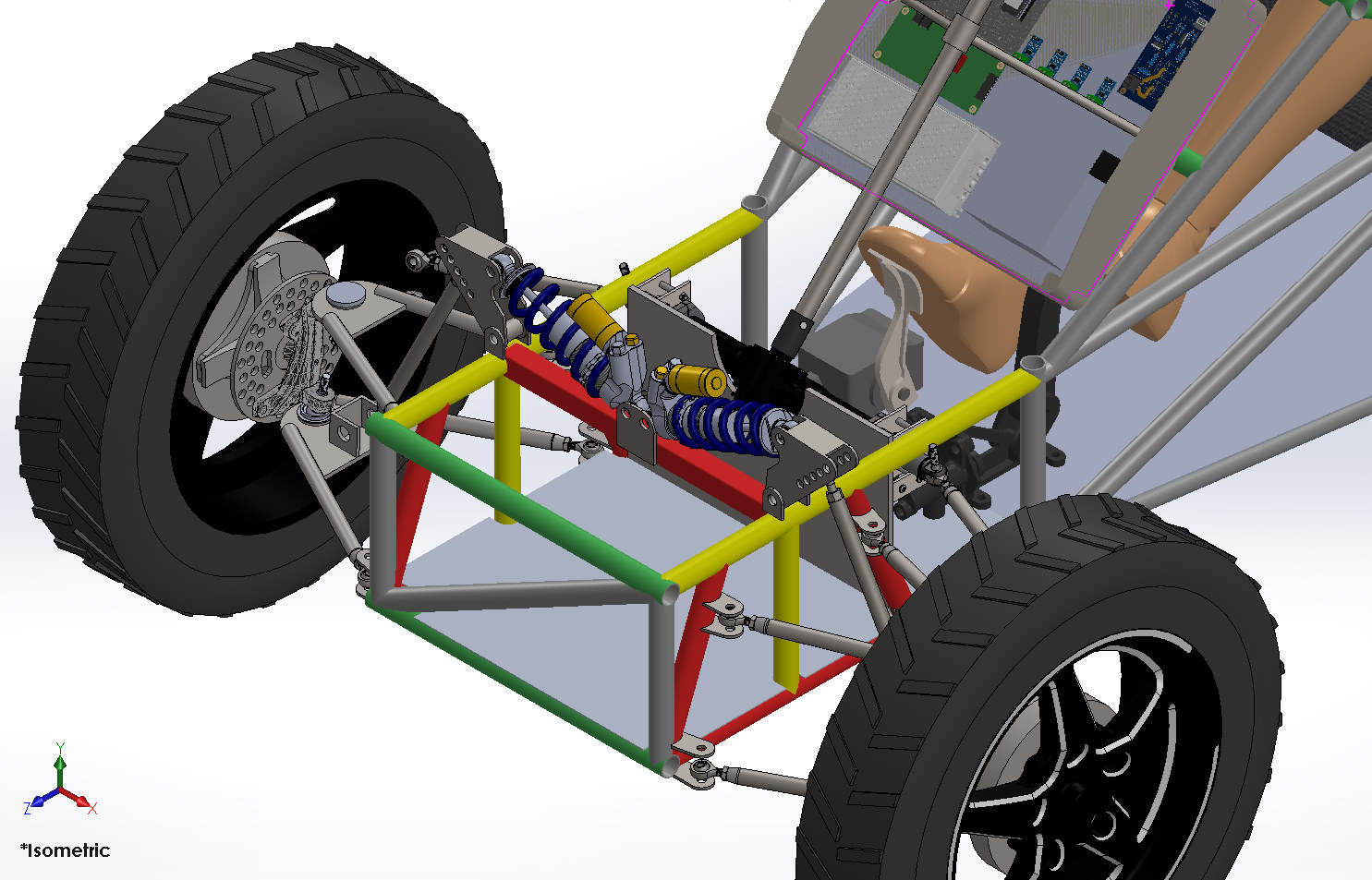
Rear trailing arm
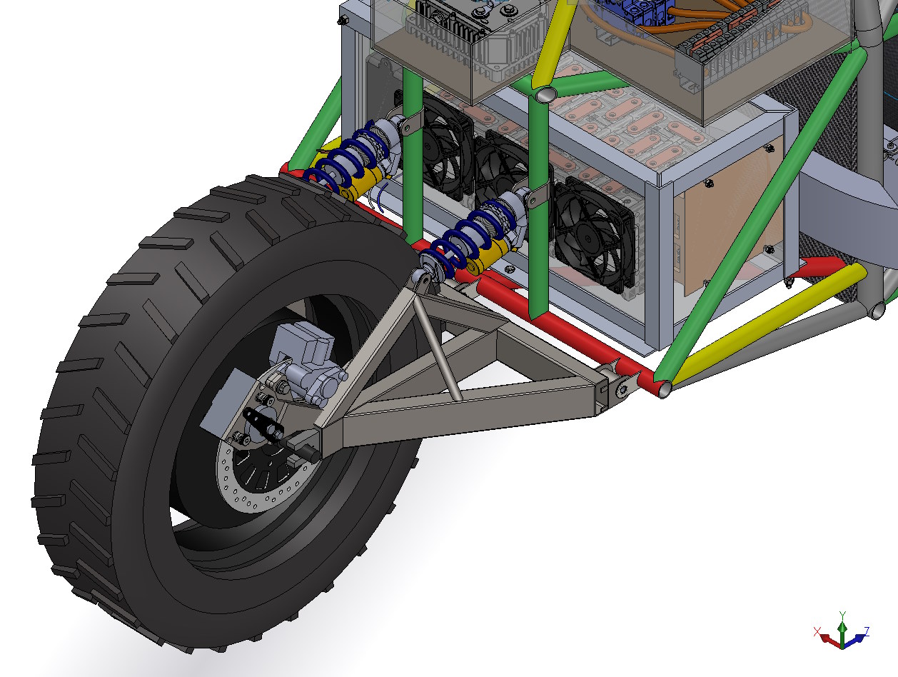
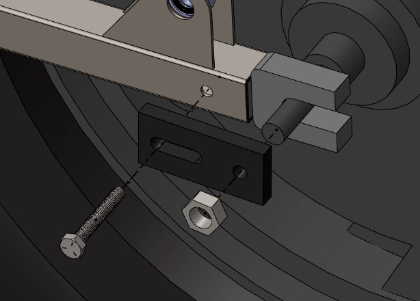
We redesigned the rear swingarm several times after I had significantly revised the rear of the car. Taking inspiration from sport touring motorcycles, I decided on a close resemblance to a dual-shock swingarm. The motor’s non-removable axle posed a challenge, but by studying how the rear wheel on a Ninja 400 motorcyle is secured, we made our own custom mounting mechanism. By using aluminum wrench pieces we machined in-house that slide into the tubing, held in place by plates and bolts on both sides, we achived a mount that is sturdy, robust, and most importantly, regulations-compliant.
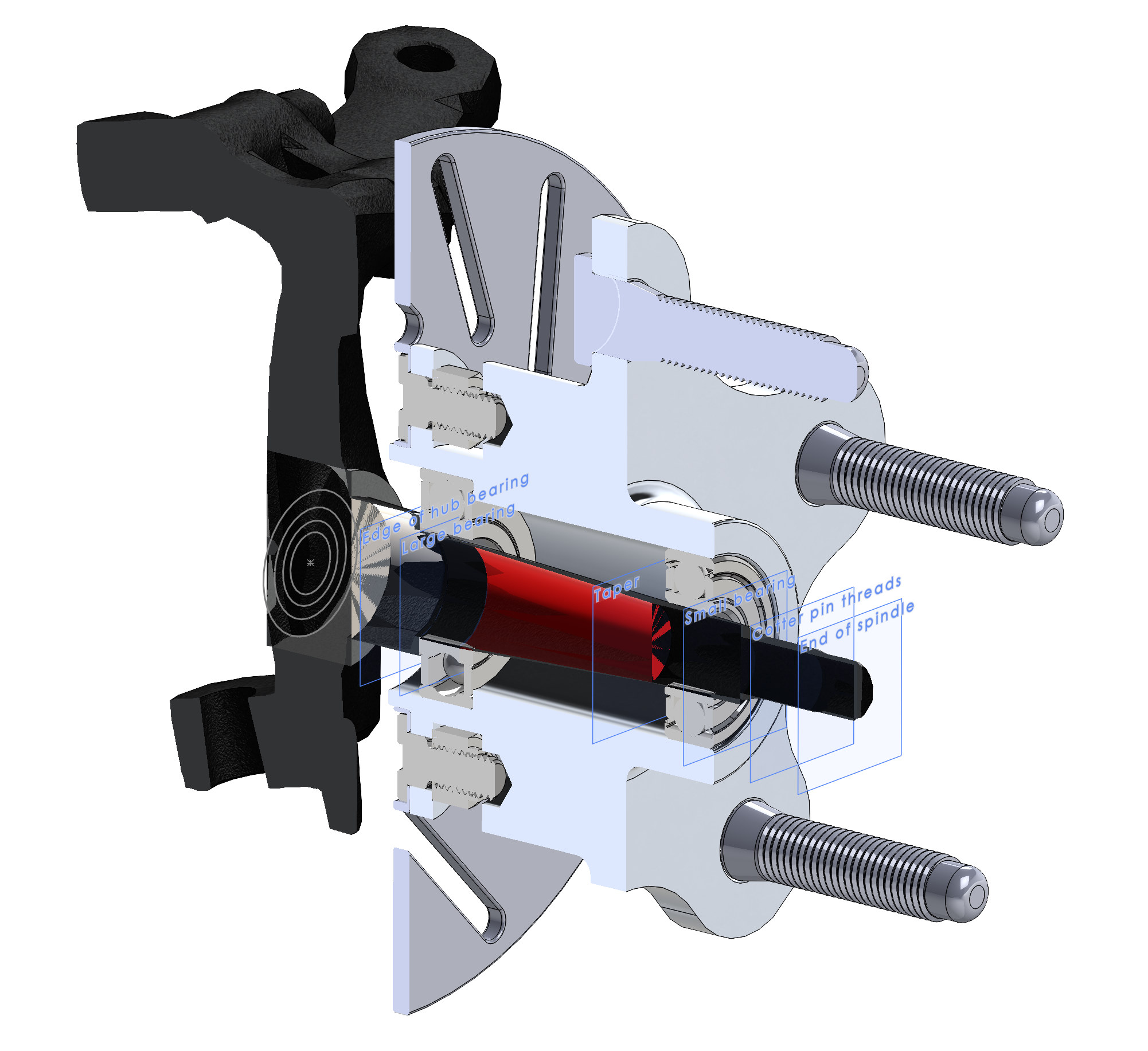
We had also designed a custom wheel hub for our existing Yamaha Banshee spindle/knuckle, but it was never manufactured due to cost and time constraints. If we had implemented this hub, it would reduce the vehicle’s scrub radius and unsprung mass by being far lighter than the off-the-shelf hub and by allowing us to remove a spacer for adapting bolt patterns.
I put a 360 camera inside the cockpit during our first test drive and dynamics testing at FSGP, which you can watch below. My team’s excitement at seeing our endless hard work pay off speaks for itself. The suspension and braking systems worked fantastically, giving the driver confidence and control authority, which is made apparent by how naturally he took to it.
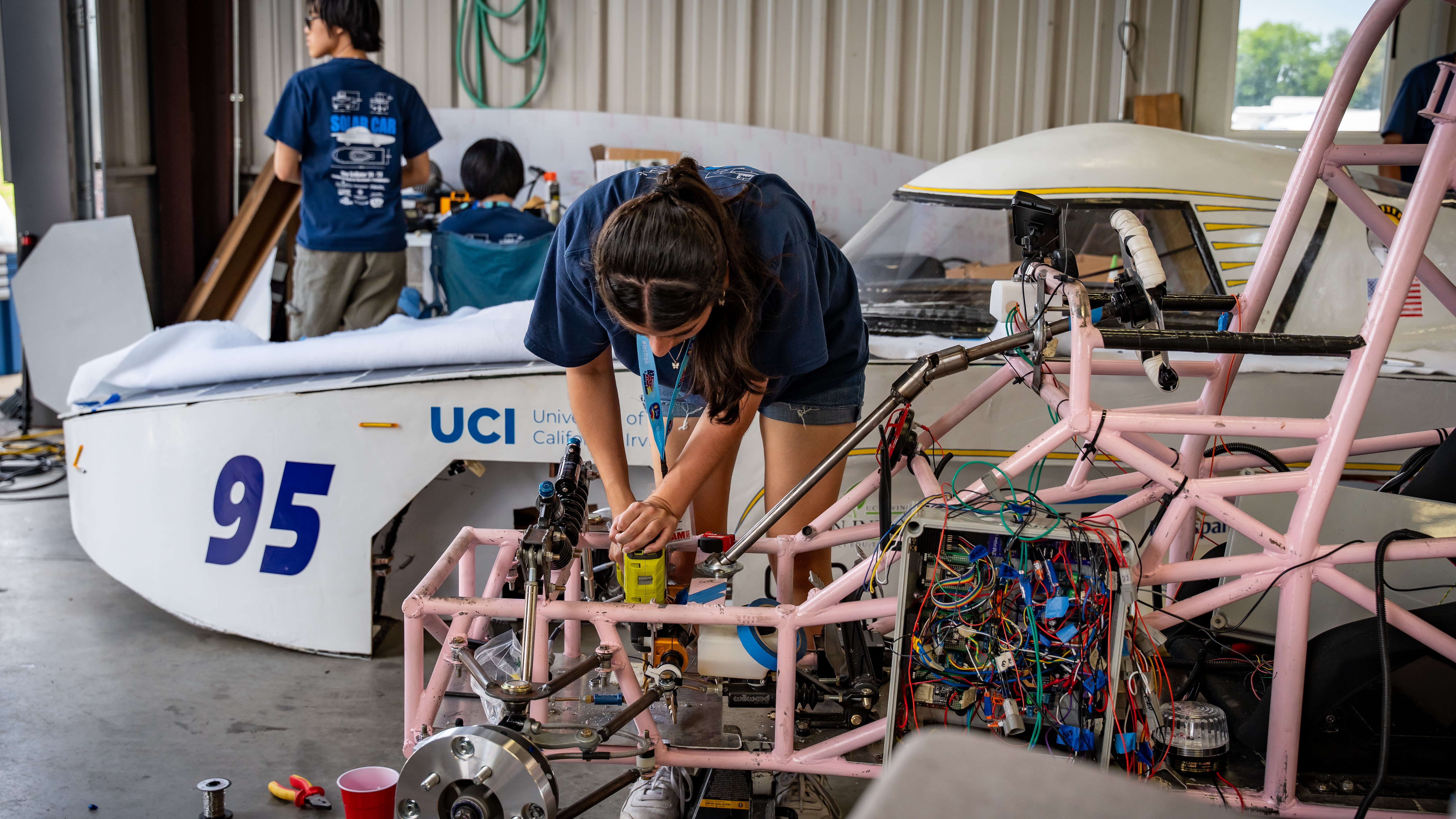
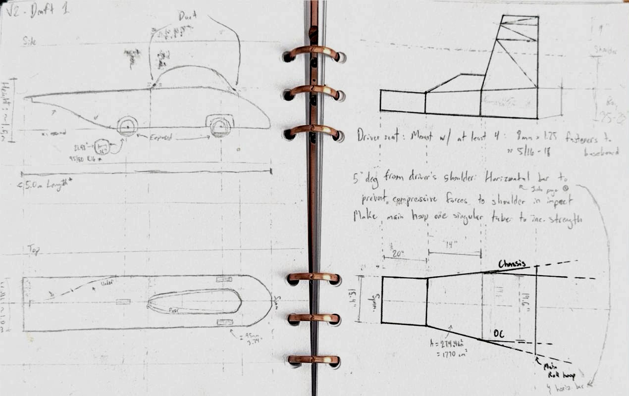
Chassis
The spaceframe chassis was designed in SolidWorks using Weldment features and constructed from 4130N chromoly steel, which was cut, bent, and notched by VR3 Engineering. This alloy offers a yield strength of 435 MPa and an ultimate tensile strength of 670 MPa. I chose chromoly over 6061 aluminum because our campus had better facilities for MIG welding, which is unsuitable for bonding aluminum. With the right geometry, the higher density of steel is compensated by its superior strength.
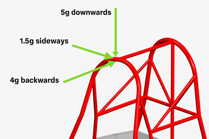
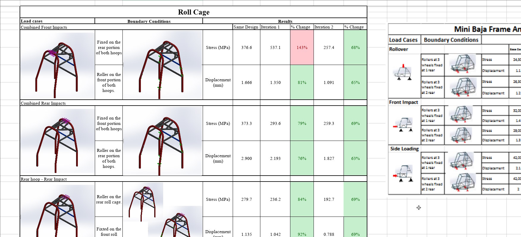
Our regulations stipulate that the entire chassis, particularly the roll cage section, must withstand multiple-G impact scenarios. An example of an impact scenario on the roll cage is a load case of 5G downwards, 1.5G sideways, and 4G backwards, simultaneously. The roll cage cannot yield in any of the ten loading cases, while the rest of the chassis (occupant cell) cannot deform anymore than 25mm, or exceed ultimate strength in its five respective loading cases. All of the load cases were analyzed in SolidWorks Simulation with static analyses on 1D or 2D meshes, as regulations require. This process took several months of trial and error, with early results being questionable or invalid, but we finally gained a better grasp of how to effectively simulate a complex structure under such conditions. The final chassis evolved from initial sketches into a highly robust, relatively lightweight, and regulation-compliant design. From this iterative process, I gained experience for material tradeoffs and structural design.
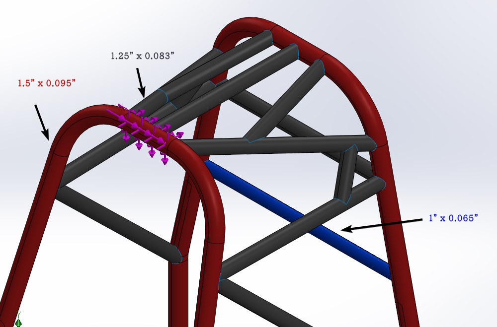
Outer diameters for our chassis tubes, particularly in the roll cage section, vary between 1.5" to 1", with thicknesses varying between 0.095" to 0.065" where suitable.
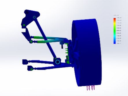
FEAs
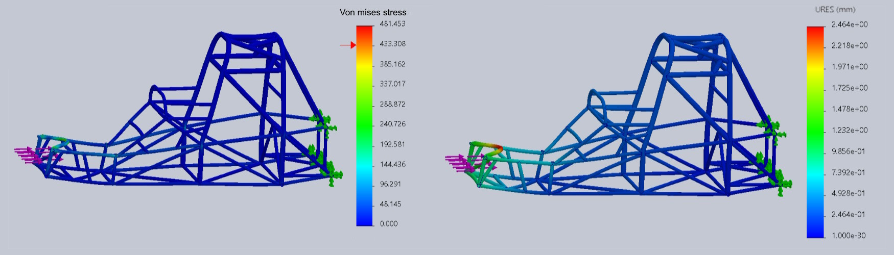
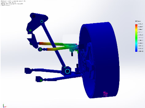
Front impact loading case simulation for occupant cell. (Left: Red elements show stress of 481 MPa, which is less than the ultimate tensile strength of 670 MPa, Right: Red elements show deformation of 2.5mm)
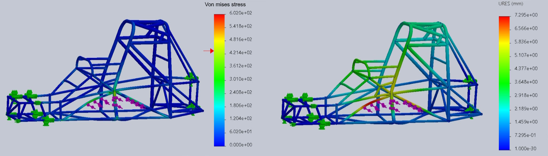
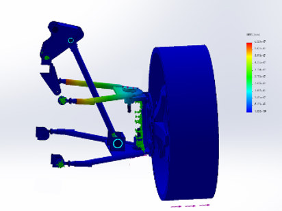
Side impact loading case simulation for occupant cell. (Left: Red elements show stress of 602 MPa, which is less than the ultimate tensile strength of 670 MPa, Right: Red elements show deformation of 7.3mm)
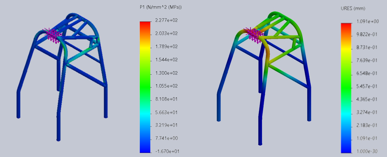
Front Roll Hoop Combined Loading (Left: Red elements show stress of 228 MPa, which is less than the yield strength of 435 MPa, Right: Red elements show deformation of 1.1mm)
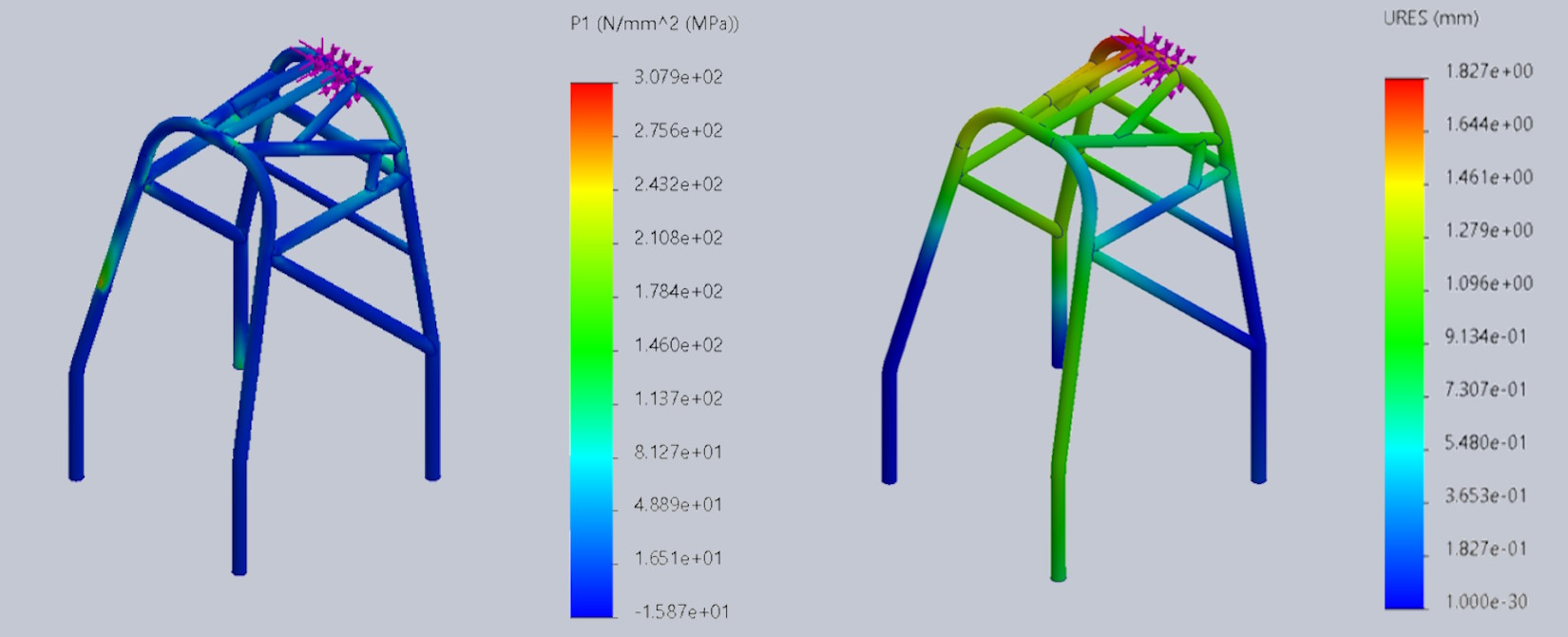
Rear Roll Cage Combined Loading (Left: Red elements show stress of 308 MPa, which is less than the yield strength of 435 MPa, Right: Red elements show deformation of 1.8mm)
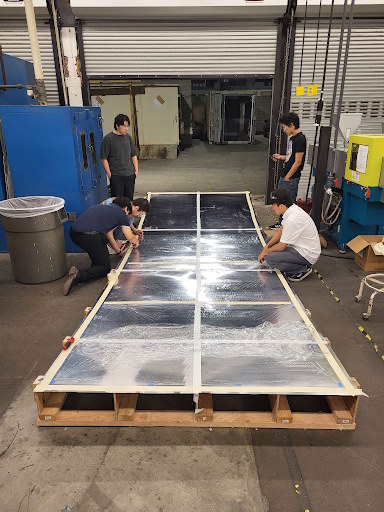
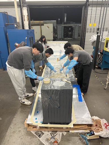
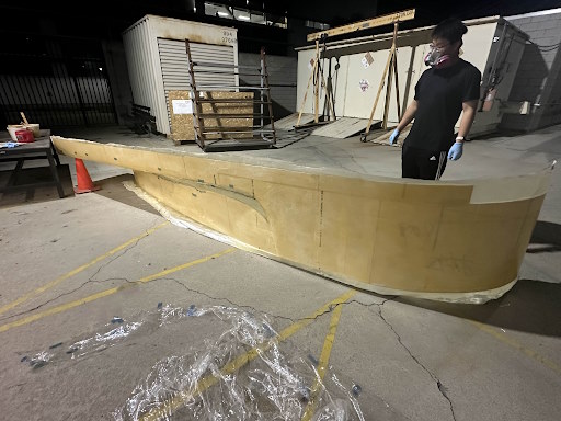
Aerobody
The aerobody consists of three distinct sections: bottom, sides, and top. Carbon-fiber honeycomb panels transfer impact forces from the aerobody to the chassis, adding rigidity under dynamic loads, and preventing undue flexing or structural failure.
Bottom shell:
Carbon-fiber honeycomb panel secured to the bottom of the chassis, with gaps for the wheels, provides a ride height of 4 inches. Side shell: Fiberglass composite, made by curing it with epoxy and vacuum bagging it on a female mold.
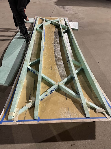
Top shell: Made with the same composite as the side shell, using its own own mold, then structurally reinforced with XPS foam serving as stringers, inspired by aircraft wing structures.
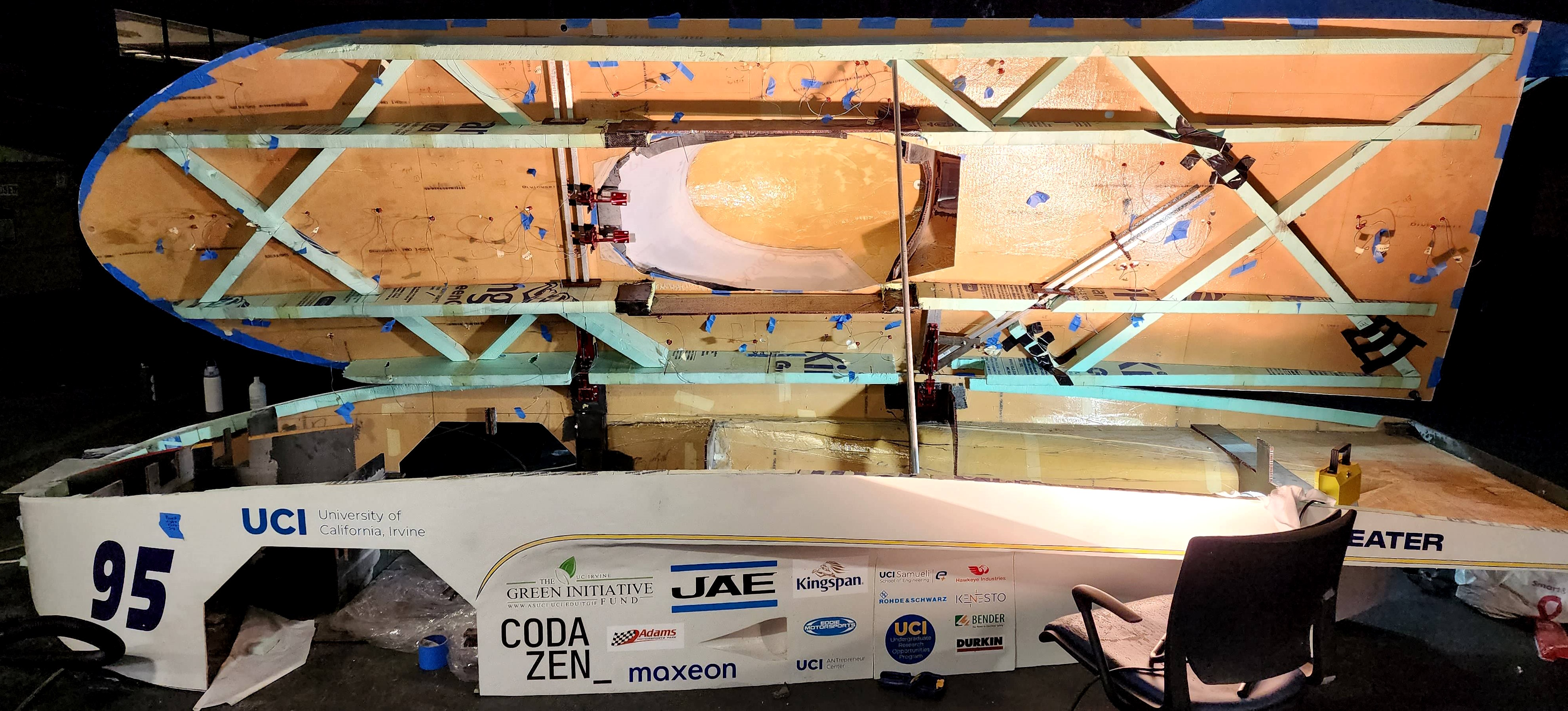
Our method of reinforcing the body with foam stringers to avoid flexing was noted by other competitors for how lightweight, simple, and cost-effective it was. None of the solar panels’ adhesion failed at any point during the movement of the car across the country or at the racetrack itself, and held up perfectly during dynamics.
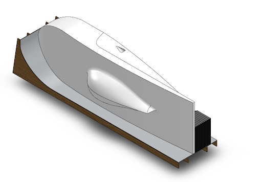
CFDs
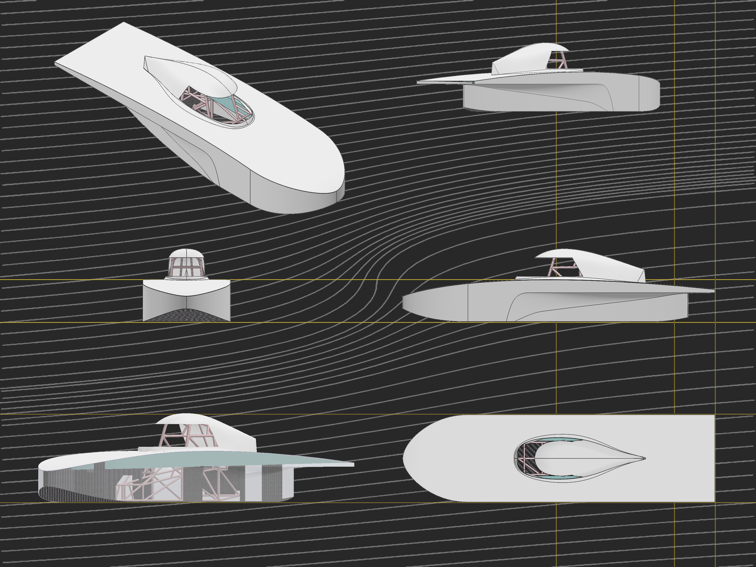
While I was developing a better understanding of how the suspension should perform, I began working on the design of the aerobody. By this point, I had sketched the aerobody by hand, but I did not yet have the skills to model it properly in CAD. Instead, I used vaguely similar shapes to conduct SolidWorks Flow Simulations. While this approach helped convey how different shapes and curves reduced drag by visualizing the particle movement, the results were not very intuitive for me at the time.
We lator pivoted to conducting CFD simulations in ANSYS, which provided results that were not only more informative but also more reliable. After many iterations, we developed a body shape with a Cd of 0.119 that produced a slight downforce under most conditions.
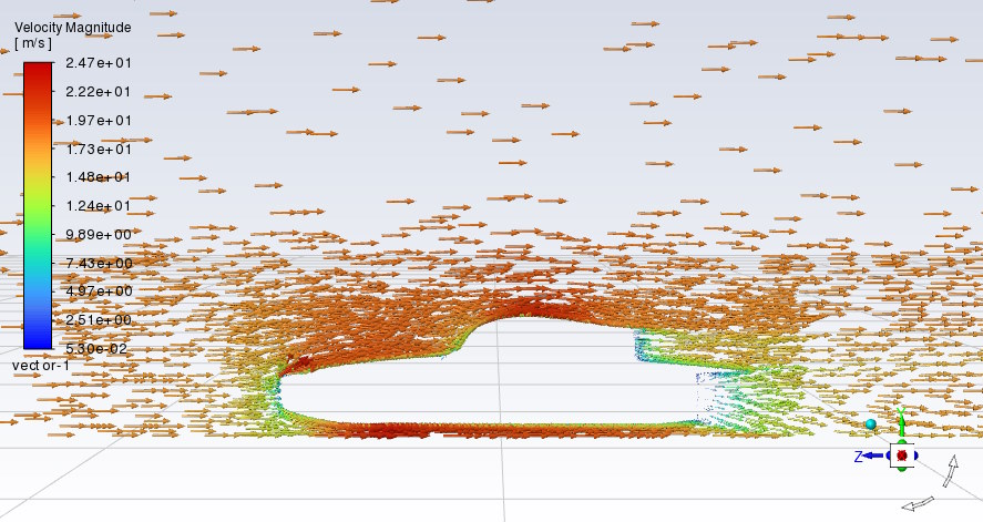
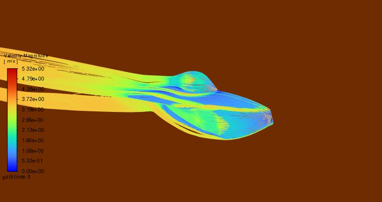
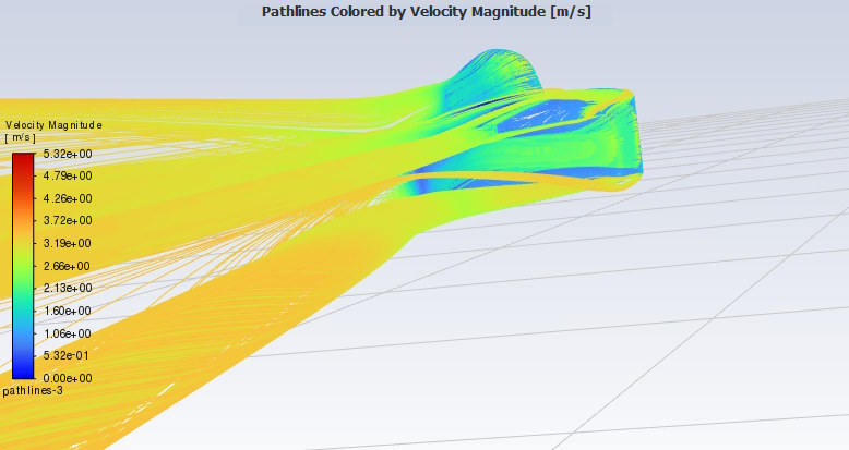
The aerobody’s drag coefficient exceeded my initial target of 0.2 by far, and was more than strong enough to keep the solar panels secure during transport to and from Kentucky, as well as around the racetrack. Looking back, I wish we had more time to consider how to leverage potential thrust from crosswinds to reduce energy usage.
An early proof-of-concept of V2 featured a preliminary aerobody design, which exhibited a slight tendency to lift. Later improvements reduced the drag coefficient, decreased the upper-to-lower pressure gradient, and introduced a slight downforce tendency.
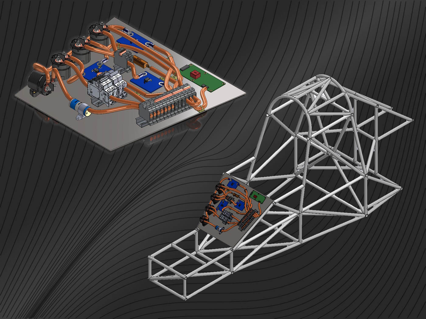
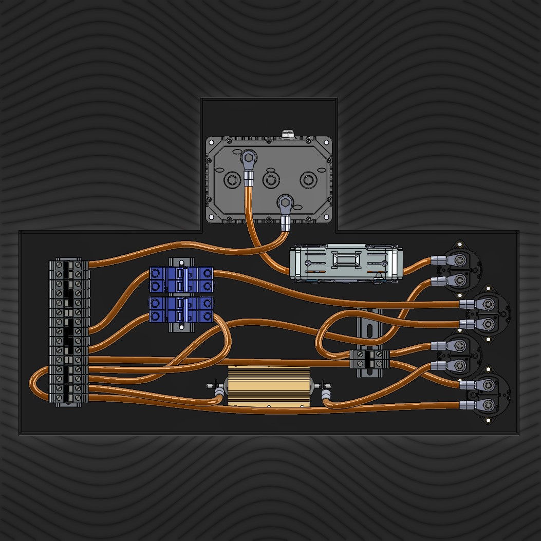
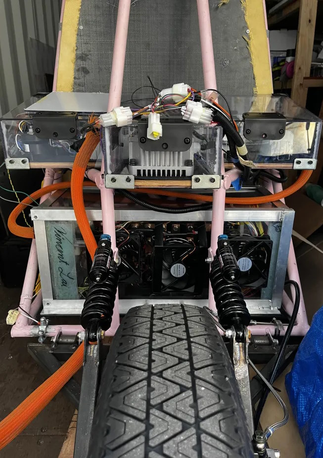
Electrical
The high-voltage subteam was challenged with arranging fuse panel components within limited physical space, while adhering to bending radius restrictions of 4 AWG power cables (rated up to 165 Amps, with thicker insulation compared to standard household wires).
To design the fuse panel, I utilized SolidWorks Electrical to create custom cables and use its library of connectors to quickly determine what layout would bend the wires within their limits and give the subteam full-scale schematics to construct a physical prototype for verification.
Validation
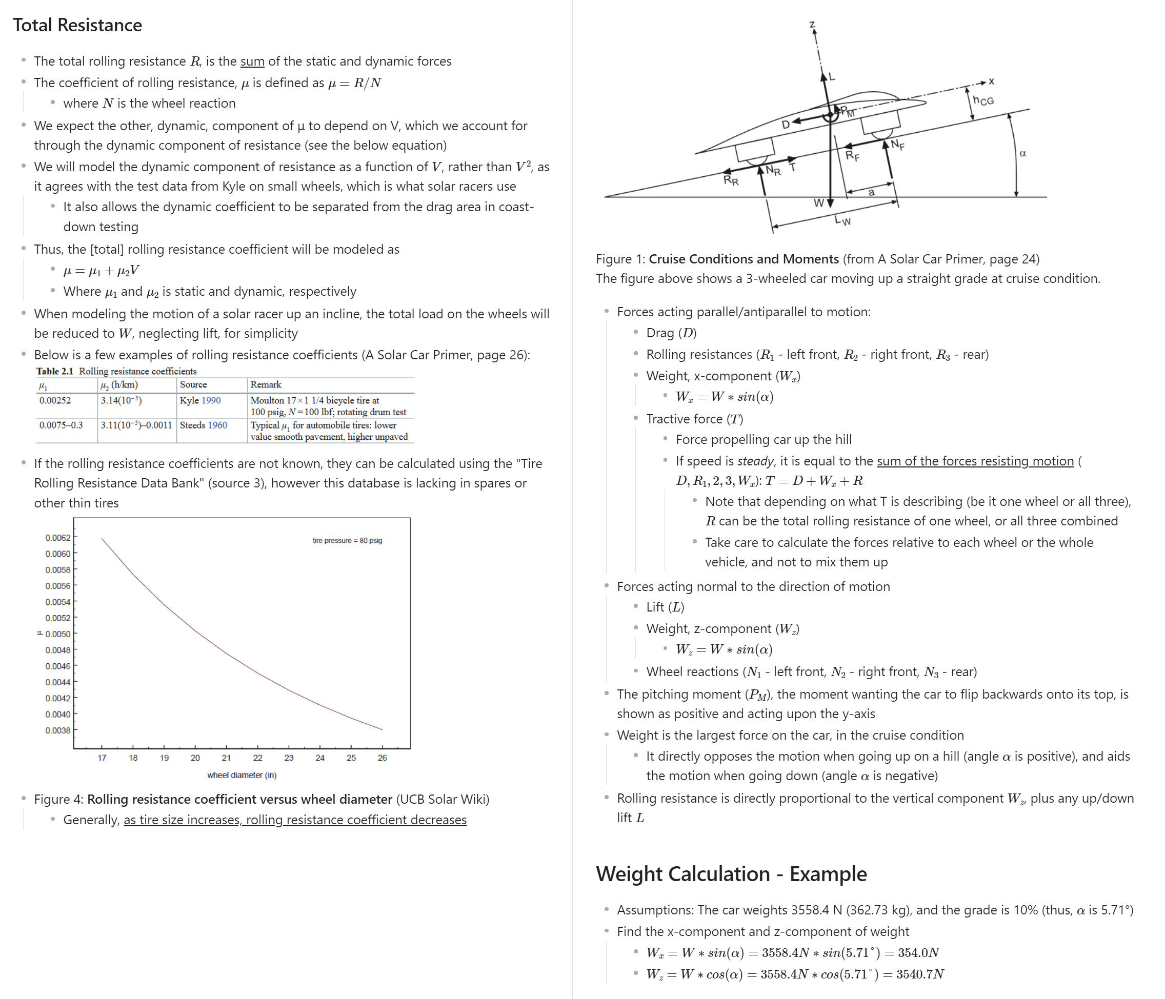
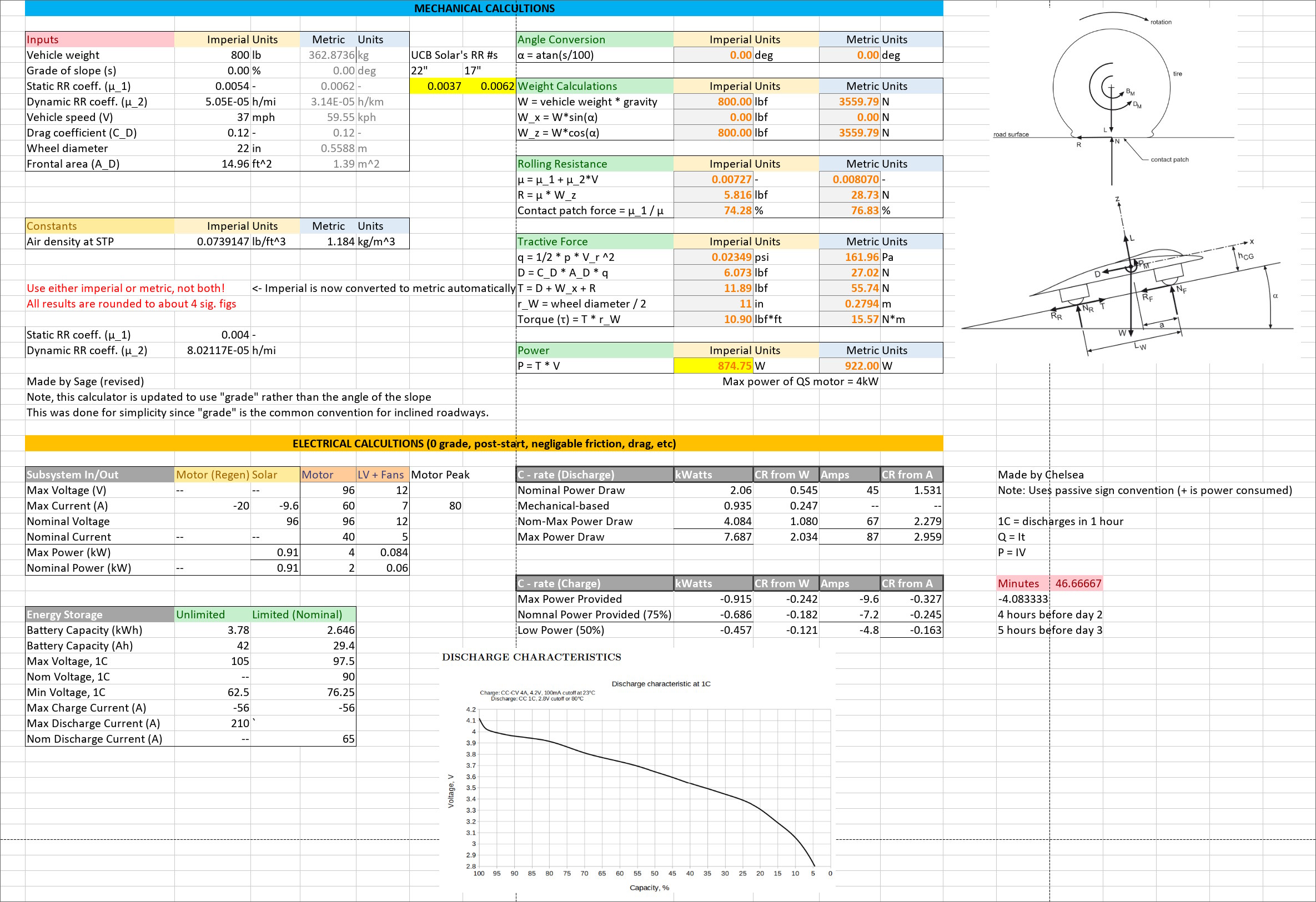 Depicted above is my most frequently used spreadsheet calculator by far. Based on research from textbooks and academic papers (see below), it automatically calculates the power required under various real-world conditions. It calculated static and dynamic rolling resistances, aerodynamic losses, inclines, and efficiency losses. This tool was used in almost every upper-management meeting to discuss issues related to weight, power management, and more. It was also instrumental in simulating our performance on different sections of the NCM racetrack, which features significant inclines.
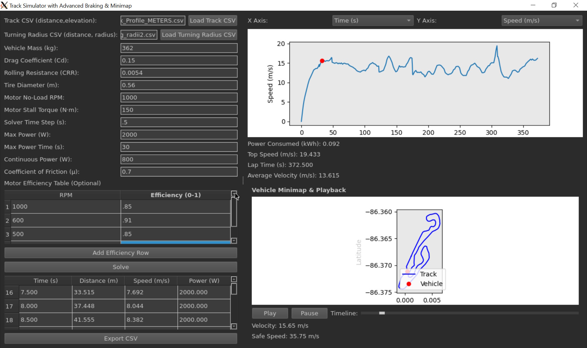
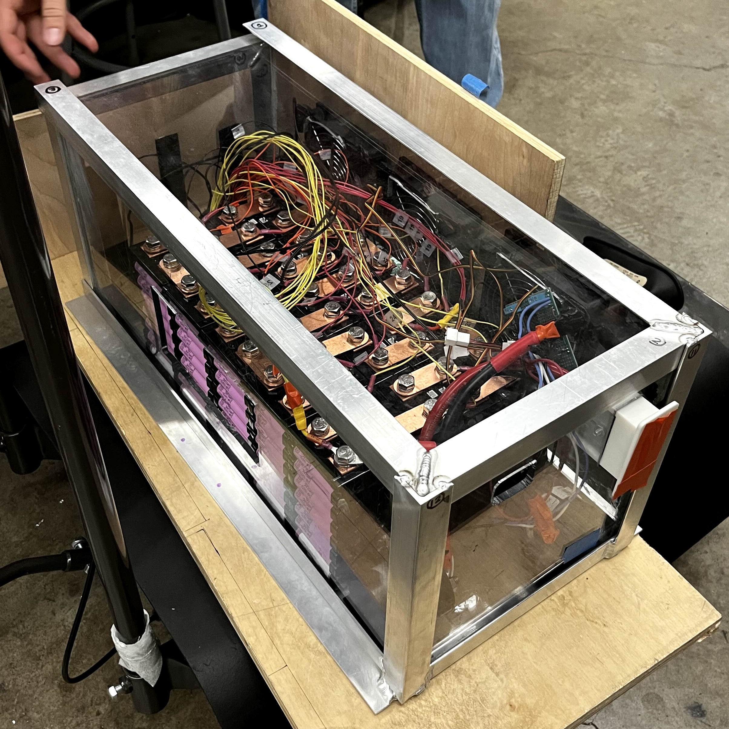
One of my suspension team members developed a track simulator, which I modified and integrated with the power calculator. By comparing lap times and specifications to our competitors, we found that we were actually quite competitive and could potentially score in the top 5, provided we optimized our pit stops—despite our relatively low battery capacity compared to top teams. (Our campus did not have the facilities to fabricate our own battery modules, so we had to assemble off-the-shelf modules.)
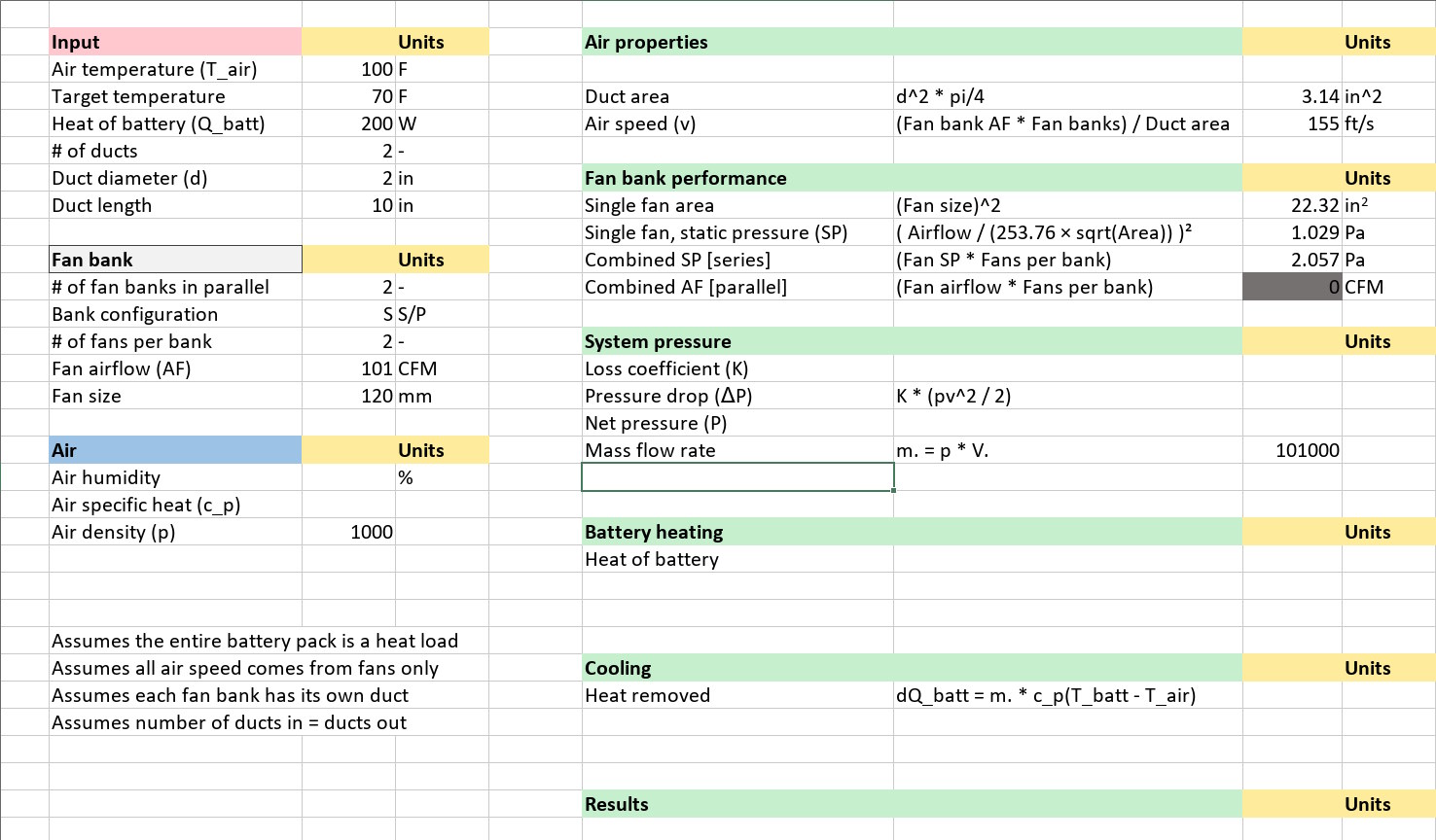
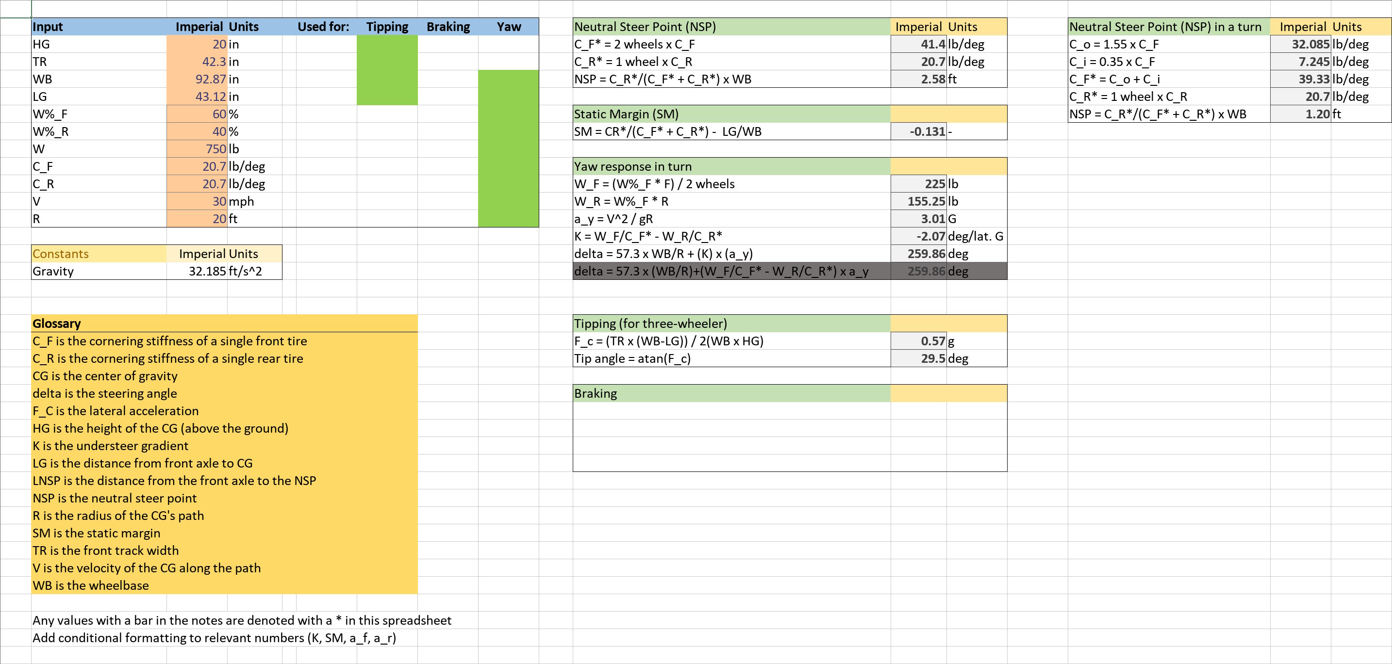
A few additional (unfinished) spreadsheet calculators focused on vehicle dynamics and battery cooling were also developed. The former helped verify the need to widen the track width to accommodate more lateral force before risking tipping under extreme dynamic conditions. The latter demonstrated to the electrical team that not only could we provide sufficient airflow to cool the battery pack, but that stacking fans in series would improve cooling performance.
A recap video of the Formula Sun Grand Prix experience, made by one of my Aerobody members: UCI FSGP 2025 | YouTube